


+86 20 84133345
+1 781 218 9688


Input Channel
With the low-noise analog pre-amplifier, the signal input of OE1022 can be switched to operate in the single-ended or differential voltage mode, and the input noise is 5 nV/√Hz. The input impedance is 10 MΩ and the full-scale input voltage sensitivity ranges from 1 nV to 1V. Besides, OE1022 can also be used for current measurements with variable current gains of 106 or 108 V/A. Two line filters (50/60 Hz and 100/120 Hz) are designed to eliminate line related interference. The programmable gain amplifier is provided to adjust the dynamic reserve of the system according to the magnitude of the input signal, so that OE1022 has inherently large dynamic reserve up to 100dB. The sampling rate of 312.5KSPS is determined by a precision 24-bit A/D converter and a specific filter is designed to avoid aliasing.
Reference Channel
In order to provide the reference signal for OE1022, an externally applied sine wave or square wave, or its owninternally synthesized reference source could be used. When the instrument is set to internal reference mode, the internal precision stabilized oscillator and the digital synthesized algorithm are used to generate sinewave output that multiplies the input signal, there is virtually no reference phase noise when choosing internal reference mode. Taking advantage of digital phase-shifting technique, the reference signal phase could be adjusted with 0.01° resolution. The internal reference mode can operate at a fixed frequency from 1 mHz to 100 kHz. In addition, the external reference is also applicable to OE1022, including the sinewave reference signal and TTL logic reference signal. The rising and trailing edge of external reference signal are applied to trigger off the internal Phase Locking Loop (PLL). Based on the frequency of reference signal, harmonic detection can be performed by OE1022. The maximum frequency of the measurable harmonics is 32767 times of basic frequency, and it is also less than the maximum operational frequency 100 kHz.
Display
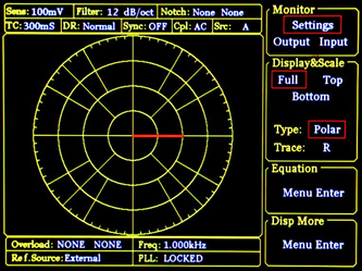
OE1022 uses the 5.6 inch 640×480 TFT color display as its screen. Data measured by OE1022, such as, X, Y, R, θ, is stored in up to four traces. Trace values can be displayed as a bar graph or as a strip chart showing the trace values as a function of time.

Besides, OE1022 can display polar plots, showing phasor composed by in-phase and quadrature components of the signal. All displays can be easily scaled by the manual operation, and the auto-scale feature is available to optimize display quickly. The screen can be configured as a single large display, or two horizontally-split displays.

![]()
Simultaneous Multiple-harmonic Measurement
The traditional phase-locked amplifier can only measure fundamental frequency signal or one certain harmonic ware at the same time, so it can not meet the requirement in some occasions when measuring multiple frequency components simultaneously is needed. In digital end, OE1022 combined FPGA and ARM technology, which has wider processing bandwidth and more flexible digital framework. The digital processing precision could reach 48 bits and could measure 3-channal harmonic components simultaneously, which makes one OE1022 is equal to three traditional phase-locked amplifiers.
Remote Operation
The built-in RS232 to USB interfaces on OE1022 allow full manual operation from a controlling computer, including setting or interrogating control and reading out data. Free LabVIEW program is provided. It makes it easy to set up and run complex experiments, such as remote control of every instrument function. The display menu offered by the LabVIEW program allows customers observe all command received and responses generated by instrument.
| Voltage Input Mode | Single-ended or Differential |
| Full-scale Sensitivity | 1 nV to 1 V in a 1-2-5 sequence; 1 fA to 1 µA |
| Current Input | 106 or 108 V/A |
| Impedance | |
| Voltage | 10 MΩ |
| Current | 1 kΩ to virtual ground |
| C.M.R.R | >100 dB to 10 kHz, decreasing |
| Dynamic Reserve | >120 dB |
| Gain Accuracy | 0.2% typ, 1% max |
| Voltage Noise | 5 nV/√Hz @ 997 Hz |
| Current Noise | 5 fA/√Hz @ 97 Hz |
| 13 fA/√Hz @ 997 Hz | |
| Line Filters | 50/60 Hz and 100/120 Hz |
| Gounding | BNC shield can be grounded or floated via 10 kΩ to ground |
| Input | |
| Frequency Range | 1 mHz to 102 kHz |
| Reference Input | TTL or Sine |
| Input Impedance | 1 MΩ |
| Square Reference Level | VIH>3V, VIL<0.5V |
| Sine Reference Signal | >1 Hz |
| > 400 mVpp | |
| Phase | |
| Resolution | 0.001° |
| Absolute Phase Error | <1° |
| Relative Phase Error | <1 mdeg |
| Drift | |
| <0.01 deg/℃ below 10 kHz | |
| <0.1 deg/℃ above 10 kHz | |
| Harmonic Detection | 2F, 3F, …nF to 102 kHz (n<32,767) |
| Acquisition Time | |
| Internal Ref. | Instantaneous acquisition |
| External Ref. | (2 cycles + 5 ms) or 40 ms, whichever is larger |
| Number of Demodulators | 3 |
| Stability | |
| Digital Outputs | no zero drift on all setting |
| Display | no zero drift on all setting |
| Harmonic Rejection | -90 dB |
| Time Constants | 10 µs to 3 ks (<200 Hz) |
| 10 µs to 30 s (>200 Hz) | |
| 6, 12, 18, 24 dB/oct | |
| Synchronous Filters | <200 Hz(18, 24 dB/oct rolloff) |
| Frequency Range | 1 mHz to 102 kHz |
| Accuracy | 2 ppm + 10 µHz |
| Resolution | 1 mHz |
| Disrortion | -80 dBc (f<10 kHz),-70 dBc (f>10 kHz) |
| Amplitude | 0.001Vrms to 5 Vrms ( Resolution:1 mVrms) |
| Accuracy | 0.5% typ (f<10 kHz), 1% max |
| Stability | 100 ppm/℃ |
| Sine Outputs | Sine signal, output impedance 50 Ω |
| TTL Outputs | 5V TTL/CMOS level, output impedance 200Ω |
| Screen | 5.6-inch, 640 X 480 TFT |
| Screen Format | Single or dual display |
| Display Quantities | Each display shows one trace, traces can be defined as X, Y, R, θ |
| Display Types | Numerical form, bar graph, polar plot and strip chart |
| Color Types | Yellow, Green |
| CH1 and CH2 Outputs | |
| Function | Output X, Y, R, θ |
| Output Voltage | ±10 V |
| Output Current | ±30 mA max |
| Update Rate | 312.5 kSa/s |
| AUX Inputs | |
| Function | 4 Channel Inputs |
| Amplitude | ±10 V,1 mV resolution ratio |
| Impedance | 1 MΩ |
| AUX Outputs | |
| Function | 4 Channel Outputs |
| Amplitude | ±10 V,1 mV resolution ratio |
| Drive Current | ±25mA max |
| Trigger Input | |
| Function | TTL external trigger is used for data storage |
| Monitor Output | |
| Function | Analog output of a signal-amplifier |
| Drive Current | ±40mA max |
| RS-232 to USB interface |
| IEEE-488 interface(optional) |
| Power Requirements | |
| Voltage | 100/120/220/240 VAC(optional) |
| Frequency | 50/60 Hz |
| Power | 30 W typ, 40 W max |
| Power Supply Rejection | 70dB@1MHz |
| Weight | 8 KG |
| Dimensions | |
| Width | 448 mm |
| Depth | |
| With Handle | 515 mm |
| Without Handle | 470 mm |
| Height | |
| With Feet | 148 mm |
| Without Feet | 133mm |
| Scanning Microscope | AFM, STM, SPM |
| Materials Science | Carrier Mobility, Carrier Density, Hall Effect, Ultrasonic Materials |
| Transport Measurement | Conductivity Measurement, Impedance Measurement |
| Noise Represents | Noise Density, Cross-Correlation Measurement |
| Optical Experiment | Spectral Analysis, Spectral Measurement, THz Measurement, TDLAS |
| Sensor Measuring | Gyroscope, Photoelectric Sensor, Resonator, Accelerometer |
| Magnetic Sensor | SQUIDs, NV Color Center, Atomic Magnetometer, VSM |
| Biomedical | Microfluidic |


| File name | Explain | Size | Version number | Download |
| OE1022 Introduction | Product Introduction Document of OE1022 Lock-in Amplifier. | 1703kb | v250418 |
Download
|
| OE1022 User Manual | Operating Manual for OE1022 Lock-in Amplifier. | 8870kb | v250814 |
Download
|
| OE1022 Control Software | OE1022 102kHz lock-in amplifier LabVIEW control platform software. | 1156kb | v20210903 |
Download
|
| Control Software Driver | This LabVIEW firmware needs to be installed first before the control software of each platform can be used. | 368275kb | v2011 |
Download
|
| OE1022 LabVIEW Development Library | The LabVIEW library functions for OE1022 only support Labview 2011 and above versions. | 451kb | v20190509 |
Download
|
| Serial Port Driver | Windows7 and 8 users need to install this driver before using USB serial ports and RS232 serial ports. | 4316kb | v.2.12.26 |
Download
|
| Serial Port Debugging Assistant | Serial port debugging assistant, facilitating the debugging of instruments. | 486kb | v3.8.3 |
Download
|
| USB_Driver for Win7/8 | Users of Windows 7 and 8 need to install the USB2.0 driver separately. | 24820kb | v1.5.0 |
Download
|