


+86 20 84133345
+1 781 218 9688


The OE4011 is a high-performance, low-noise voltage preamplifier featuring a JFET input. It provides a high input bandwidth from DC to 5 MHz and supports both AC and DC coupling, as well as single-ended and differential input modes. The differential output architecture enhances noise immunity and effectively suppresses DC bias.
The OE4011 integrates a 4-level selectable gain ranging from 20 dB to 80 dB. Its 8-level filter adjustment includes seven precision 2nd-order low-pass filter stages and one Full Bandwidth (FBW) setting. Furthermore, the device is equipped with an offset adjustment function and supports a maximum output swing of ±10 V. At a frequency of 10 kHz, the equivalent input voltage noise is as low as approximately 3 nV/√Hz, with a Common-Mode Rejection Ratio (CMRR) reaching up to 113 dB, maintaining stable performance even in the high-frequency range. A high input impedance of 10 MΩ effectively minimizes the loading effect on the input signal source.

Select the Appropriate Gain Setting. During measurement, select the correct gain setting for the OE4011. Please note that each gain setting corresponds to a specific maximum input range. Users can calculate the expected output voltage based on the selected gain value. To achieve an optimal Signal-to-Noise Ratio (SNR), it is recommended to select the most suitable gain setting and bandwidth range, provided that the peak output voltage does not exceed ±9.5 V.

2nd-Order Low-Pass Filter. The OE4011 integrates a precision-designed, 8-level 2nd-order low-pass filter. The settings can be switched using the "Filter Cutoff" knob on the side panel, with cutoff frequencies ranging from 1 Hz to 1 MHz. By effectively attenuating high-frequency noise outside the target bandwidth, this filter significantly improves the Signal-to-Noise Ratio (SNR), ensuring excellent signal purity when measuring weak voltage signals. Additionally, the device provides a dedicated FBW (Full Bandwidth) setting, allowing users to fully utilize the original DC to 5 MHz bandwidth response when capturing broadband transient signals.

Single-Ended and Differential Modes. The OE4011 provides switchable single-ended and differential input modes. Setting the Source switch to A activates single-ended mode, where the negative terminal of the signal is connected to the amplifier's internal ground via the SMB connector shield, making it suitable for basic connections and single-ended signal sources. Conversely, setting the switch to A-B selects differential mode, which requires a two-wire connection to the signal source. Combined with the OE4011's differential output architecture, this mode delivers superior noise immunity and enhanced signal quality, making it highly ideal for long-cable routing or environments with high electromagnetic interference (EMI).
AC and DC Coupling. The OE4011 allows users to select either AC or DC coupling at the input stage via the Coupling switch. DC coupling passes the entire input signal without blocking any frequency components and is strongly recommended for low-frequency measurements. However, when operating in this mode, users must be mindful of the input signal's DC offset to avoid signal saturation and clipping. Alternatively, AC coupling is designed to block the DC component of the input signal and effectively filter out low-frequency drift.
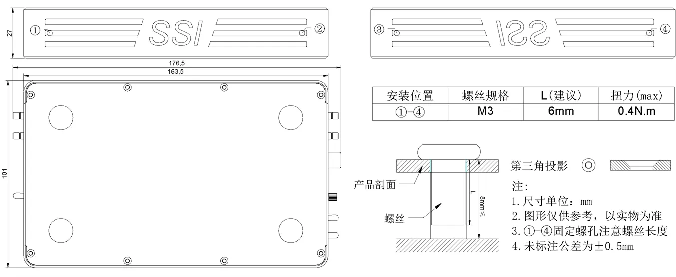
Mounting holes for test bench installation are located on the side panels of the device. Please note that there are strict limitations on the length of the mounting screws. Refer to the dimensional drawing for the specified screw length.
| Power Supply | |
| Nominal Value | 12V |
| Input | |
| Input Mode | Single-Ended/Differential |
| Input Type | JFET |
| Filter Settings | FBW、1Hz、10Hz、100H、z1kHz、10kHz、100kHz、1MHz |
| Gain Settings | 20dB、40dB、60dB、80dB |
| CMRR(10kHz) | 113dB |
| Maximum Input Voltage | 2 Vpp |
| Input Noise | 3nV/√Hz |
| Input Impedance | 1k-1GΩ(optional) |
| Input Coupling | DC/AC |
| Output | |
| Output Mode | Differential |
| Maximum Output Voltage | 20 Vpp |
| Bandwidth | DC - 5MHz |
| Output Impedance | 50Ω |
| Gain Accuracy | 2% max |
| Dimensions(mm) | 176.5*101*27(Including terminals) |
| Weight | 570g |
| Storage Temperature | -20 ℃ - 65 ℃ |
| Operating Temperature | 5 ℃ - 40 ℃ |
| Specified Temperature | 25 ℃ |
| Power Requirements | 12V/3A |
| Power Consumption | 8W max |
| Connectors | 2 SMB input |
| 2 SMB output | |
| DC Power Receptacle (5.5-2.1 mm) |
| 1 × 12 V, 3 A DC Power Adapter |
| 2 × SMB-to-BNC Cables |
Full Bandwidth Gain Setting Test
Test Conditions: Supply Voltage = 12 V, Ambient Temperature = 25°C, AC Coupling, Single-Ended Input, Vout = 1 Vrms.
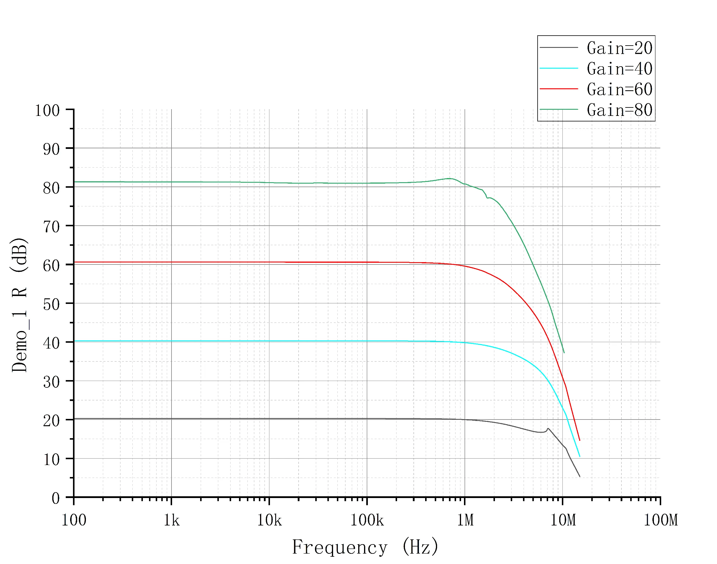
Fig.1 Full Bandwidth Frequency Response
Filter Setting Test
Test Conditions: Supply Voltage = 12 V, Ambient Temperature = 25°C, Input Signal = 100 mVrms, Gain = 20 dB, AC Coupling, Single-Ended Input.
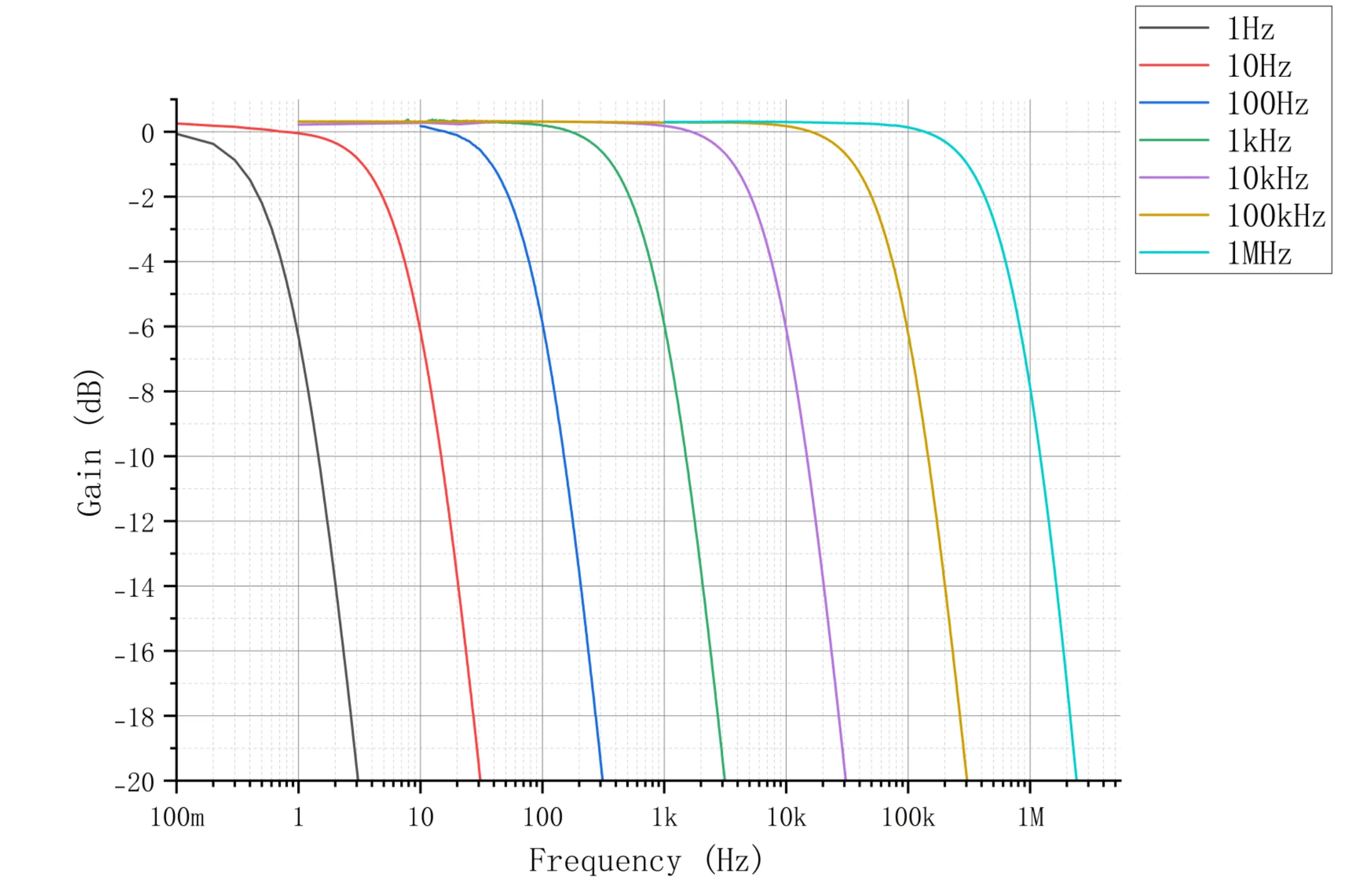
Fig.2 Filter Frequency Response
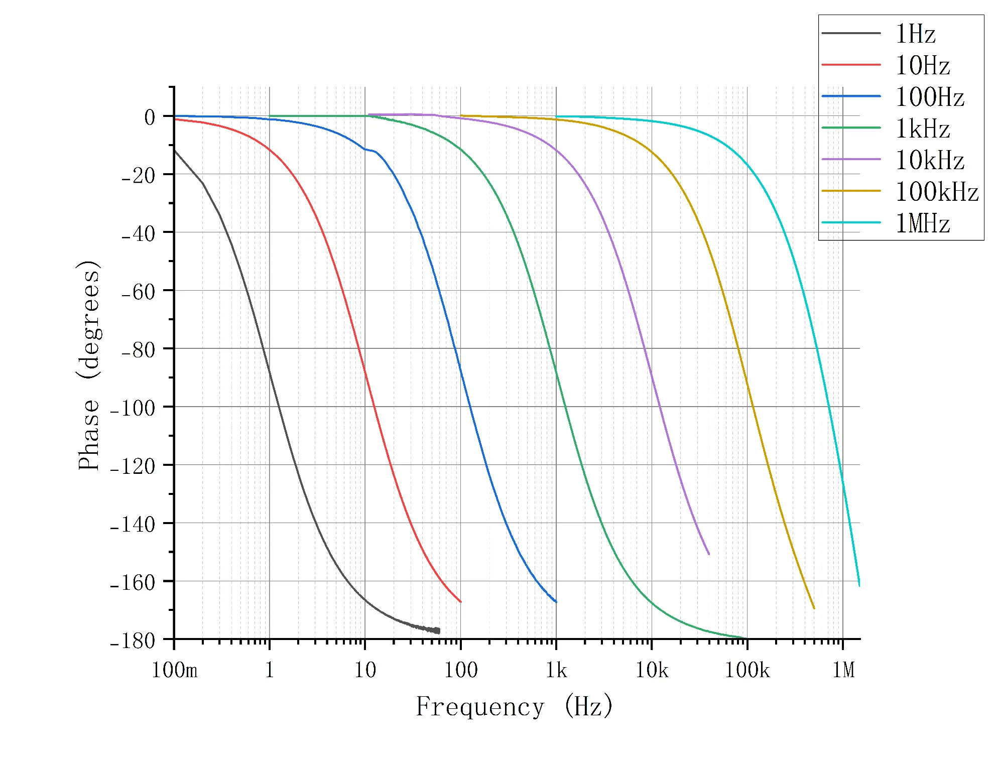
Fig.3 Filter Phase Response
| File name | Explain | Size | Version number | Download |